Cloud chamber
| Antimatter |
|---|
 |
|
Concepts and phenomena
|
|
People and bodies
|
A cloud chamber, also known as a Wilson cloud chamber, is a particle detector used for visualizing the passage of ionizing radiation.

A cloud chamber consists of a sealed environment containing a supersaturated vapor of water or alcohol. An energetic charged particle (for example, an alpha or beta particle) interacts with the gaseous mixture by knocking electrons off gas molecules via electrostatic forces during collisions, resulting in a trail of ionized gas particles. The resulting ions act as condensation centers around which a mist-like trail of small droplets form if the gas mixture is at the point of condensation. These droplets are visible as a "cloud" track that persists for several seconds while the droplets fall through the vapor. These tracks have characteristic shapes. For example, an alpha particle track is thick and straight, while a beta particle track is wispy and shows more evidence of deflections by collisions.
Cloud chambers were invented in the early 1900s by the Scottish physicist Charles Thomson Rees Wilson. They played a prominent role in experimental particle physics from the 1920s to the 1950s, until the advent of the bubble chamber. In particular, the discoveries of the positron in 1932 (see Fig. 1) and the muon in 1936, both by Carl Anderson (awarded a Nobel Prize in Physics in 1936), used cloud chambers. Discovery of the kaon by George Rochester and Clifford Charles Butler in 1947, also was made using a cloud chamber as the detector. In each of these cases, cosmic rays were the source of ionizing radiation. Yet they were also used with artificial sources of particles, for example in radiography applications as part of the Manhattan Project.
Invention
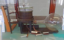
Charles Thomson Rees Wilson (1869–1959), a Scottish physicist, is credited with inventing the cloud chamber. Inspired by sightings of the Brocken spectre while working on the summit of Ben Nevis in 1894, he began to develop expansion chambers for studying cloud formation and optical phenomena in moist air. Very rapidly he discovered that ions could act as centers for water droplet formation in such chambers. He pursued the application of this discovery and perfected the first cloud chamber in 1911. In Wilson's original chamber (See Fig. 2) the air inside the sealed device was saturated with water vapor, then a diaphragm was used to expand the air inside the chamber (adiabatic expansion), cooling the air and starting to condense water vapor. Hence the name expansion cloud chamber is used. When an ionizing particle passes through the chamber, water vapor condenses on the resulting ions and the trail of the particle is visible in the vapor cloud. Wilson received half the Nobel Prize in Physics in 1927 for his work on the cloud chamber (the same year as Arthur Compton received half the prize for the Compton Effect). This kind of chamber is also called a pulsed chamber because the conditions for operation are not continuously maintained. Further developments were made by Patrick Blackett who utilised a stiff spring to expand and compress the chamber very rapidly, making the chamber sensitive to particles several times a second. A cine film was used to record the images.
The diffusion cloud chamber was developed in 1936 by Alexander Langsdorf. This chamber differs from the expansion cloud chamber in that it is continuously sensitized to radiation, and in that the bottom must be cooled to a rather low temperature, generally colder than −26 °C (−15 °F). Instead of water vapor, alcohol is used because of its lower freezing point. Cloud chambers cooled by dry ice or Peltier effect thermoelectric cooling are common demonstration and hobbyist devices; the alcohol used in them is commonly isopropyl alcohol or methylated spirit.
Structure and operation


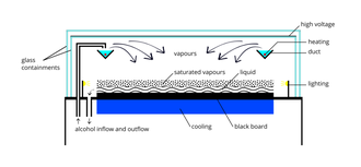
Diffusion-type cloud chambers will be discussed here. A simple cloud chamber consists of the sealed environment, a warm top plate and a cold bottom plate (See Fig. 3). It requires a source of liquid alcohol at the warm side of the chamber where the liquid evaporates, forming a vapor that cools as it falls through the gas and condenses on the cold bottom plate. Some sort of ionizing radiation is needed.
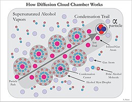
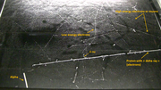
Isopropanol, methanol, or other alcohol vapor saturates the chamber. The alcohol falls as it cools down and the cold condenser provides a steep temperature gradient. The result is a supersaturated environment. As energetic charged particles pass through the gas they leave ionization trails. The alcohol vapor condenses around gaseous ion trails left behind by the ionizing particles. This occurs because alcohol and water molecules are polar, resulting in a net attractive force toward a nearby free charge (See Fig. 4). The result is a misty cloud-like formation, seen by the presence of droplets falling down to the condenser. When the tracks are emitted from a source, their point of origin can easily be determined. Fig. 5 shows an example of an alpha particle from a Pb-210 pin-type source undergoing Rutherford scattering.
Just above the cold condenser plate there is a volume of the chamber which is sensitive to ionization tracks. The ion trail left by the radioactive particles provides an optimal trigger for condensation and cloud formation. This sensitive volume is increased in height by employing a steep temperature gradient, and stable conditions. A strong electric field is often used to draw cloud tracks down to the sensitive region of the chamber and increase the sensitivity of the chamber. The electric field can also serve to prevent large amounts of background "rain" from obscuring the sensitive region of the chamber, caused by condensation forming above the sensitive volume of the chamber, thereby obscuring tracks by constant precipitation. A black background makes it easier to observe cloud tracks, and typically a tangential light source is needed to illuminate the white droplets against the black background. Often the tracks are not apparent until a shallow pool of alcohol is formed at the condenser plate.
If a magnetic field is applied across the cloud chamber, positively and negatively charged particles will curve in opposite directions, according to the Lorentz force law; strong-enough fields are difficult to achieve, however, with small hobbyist setups.
Other particle detectors
The bubble chamber was invented by Donald A. Glaser of the United States in 1952, and for this, he was awarded the Nobel Prize in Physics in 1960. The bubble chamber similarly reveals the tracks of subatomic particles, but as trails of bubbles in a superheated liquid, usually liquid hydrogen. Bubble chambers can be made physically larger than cloud chambers, and since they are filled with much-denser liquid material, they reveal the tracks of much more energetic particles. These factors rapidly made the bubble chamber the predominant particle detector for a number of decades, so that cloud chambers were effectively superseded in fundamental research by the start of the 1960s.
A spark chamber is an electrical device that uses a grid of uninsulated electric wires in a chamber, with high voltages applied between the wires. Energetic charged particles cause ionization of the gas along the path of the particle in the same way as in the Wilson cloud chamber, but in this case the ambient electric fields are high enough to precipitate full-scale gas breakdown in the form of sparks at the position of the initial ionization. The presence and location of these sparks is then registered electrically, and the information is stored for later analysis, such as by a digital computer.
Similar condensation effects can be observed as Wilson clouds, also called condensation clouds, at large explosions in humid air and other Prandtl–Glauert singularity effects.
See also
- Nuclear emulsion – also used to record and investigate fast charged particles
- Bubble chamber
- Spark chamber
- Gilbert U-238 Atomic Energy Laboratory science kit for children (1950–1951)
- Contrail
- Das Gupta, N. N.; Ghosh S. K. (1946). "A Report on the Wilson Cloud Chamber and its Applications in Physics". Reviews of Modern Physics. 18 (2): 225–365. Bibcode:1946RvMP...18..225G. doi:10.1103/RevModPhys.18.225.
Gallery
A Home Made Cloud Chamber.
Cloud chamber with visible tracks from ionizing radiation (short, thick: α-particles; long, thin: β-particles). See also Animated Version
Video of a Cloud chamber in action
Cloud chamber with cloud tracks created by particles of ionising radiation (Image taken after injection of radon)
Video of a Wilson chamber
External links
- Archived 2014-09-14 at the Wayback Machine, Peter Wothers, Royal Institution, December 2012]
| Authority control: National |
|---|


