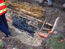
Cable fault location
Cable fault location is the process of locating periodic faults, such as insulation faults in cables. In this process, mobile shock discharge generators are among the devices used.
Cable faults
Cable faults are damage to cables which effect a resistance in the cable. If allowed to persist, this can lead to a voltage breakdown. There are different types of cable faults, which must first be classified before they can be located. The insulation of the cable plays a significant role in this. While paper-impregnated cables are particularly susceptible to external chemical and thermal influences, in high-voltage PE or XLPE cables the polyethylene insulation of the conductor is affected, leading to partial breakdowns and cracks that “eat away” the insulation.
Screening faults
A contact between conductor and screen generates a varying resistance.
Phase faults
The contact between multiple conductors generates a varying resistance.
Sheath faults
Sheath faults are damage of the cable sheath that allows the surroundings contact with the cable screen.
Faults due to moisture
Water penetrates into the cable sheath and contacts the conductors. Impedance changes at the fault location make measuring more difficult. The resistance usually lies in the high-ohmic range.
Disruptions
Combination of series and parallel resistances, usually in the form of a wire break. The voltage is interrupted, i.e. Ω=∞ .
Cable testing
To locate a fault in the cable, the cable must first be tested for faults. Cable testing is therefore usually performed first in cable fault location. During the cable test, flash-overs are generated at the weak points in the cable, which can then be localised.
Locating the cable fault
The measures necessary for determining fault locations can be subdivided into individual steps.
Fault classification
Insulation and resistance measurement provides information on the fault characteristics. An insulation test measures the insulation resistance between conductor and screen; from the periodic measurement of resistance you can derive the absorption properties of the insulating material.
Pre-location
Pre-location is used to determine the fault distance. There are predominantly two methods for this.
Pulse reflection method
A pulse induced at the starting end of the cable reaches the cable fault with a speed of v/2 and then is reflected back toward the starting end of the cable. The elapsed time multiplied by the diffusion speed v/2 gives the distance to the source of the fault. See also: Time-domain reflectometer.
Transient method
In the transient method, a breakdown is triggered at the cable fault. This effects a low-resistance short circuit for a few milliseconds. This in turn produces two travelling waves diffusing in opposite directions. These waves are reflected at the cable ends so that they then travel toward each other again in the direction of the cable fault. The waves are unable to pass the fault because of the arc produced by the short circuit, so they are therefore reflected back again as with the pulse reflection method, which due to the burning short circuit results in a reversal of polarity. There are various ways to decouple and analyse these transients.
Route tracing and pinpointing
Route tracing is used to determine where the faulty cable lies and pinpointing is the process of determining the exact position of the cable fault.
Cable identification
In cable identification, the faulty cables are identified from the fault-free cables at the already determined site.
Loop tests for locating faults in underground cables
In addition to pulse reflection method and transient method, there are two popular loop tests for finding the location of faults in underground cables.
Murray loop test
Murray loop test employs the principle of wheatstone bridge for locating the fault. To perform this test, it is necessary to have a sound cable running alongside the faulty cable. One end of the faulted cable is connected through a pair of resistors to the voltage source. Also a null detector is connected. The other end of the cable is shorted. The circuit is shown in the figure at right. The bridge is brought to balance by changing the values of RB1 and RB2. Then the distance to the fault location is calculated by solving the bridge equation. See also: Murray loop bridge
Varley loop test
The similar Varley loop uses fixed resistors for RB1 and RB2, and inserts a variable resistor in the faulted leg. Test sets for cable testing can be connected for either bridge technique. If the fault resistance is high, the sensitivity of the Murray bridge is reduced and the Varley loop may be more suitable.
Fault conversion
After the cable fault is identified and located, it is then possible to “burn it in” using burner devices, in other words to convert it from a high-impedance fault to a low-impedance fault. For this a Burn Down Instrument, such as Baur ATG2 Burn Down Transformer or a similar device, can be used. A Burn Down Instrument has a Voltage Generator connected via Transformer and allows individual control of output voltage and current, a vital step for burning down High Impedance Faults.
Cable test van
The conventionally used aid in cable fault testing and location is the cable test van. The van is installed with conventional cable measuring systems for quickly reaching the location of any cable fault. In 20 years that followed, over 2000 fault location vehicles were manufactured, more than half of which were intended for the former USSR. These methods of cable fault location quickly became established in Western Europe as well.


